Home › Unlabelled ›
Series Test Lamp Circuit Diagram - How to Make Electric Series Parallel Testing Board for ... : As an example, for a 12 volt light, you can run a maximum of 3 white leds in series at full power (3.6 x 3.
Series Test Lamp Circuit Diagram - How to Make Electric Series Parallel Testing Board for ... : As an example, for a 12 volt light, you can run a maximum of 3 white leds in series at full power (3.6 x 3.. Series lamp kaise banaye 2. Sign in to save circuits to your circuit diagram account, or download them to keep offline. When b is pressed in the given circuit, the capacitor (c)$. In this video, you can. Leds consume less power and have long life when compared with fluorescents and tube lights.
The circuit playground express can stay connected via usb power from either a wall adapter or computer's hub. In this video, you can see connection of series. Electric circuits like ac lighting circuit, battery charging circuit, energy meter, switch circuit, air conditioning if the switch is on, the electric circuit is closed and the lamp glows, and if the switch is off, it will disconnect the power it consists of a galvanometer connected in series with a resistance. Take current i as the reference as shown in the figure above. Hi dosto please gyan infinity ko subscribe kar dena 4000 target ko achieve kar na hai, comments be kare.
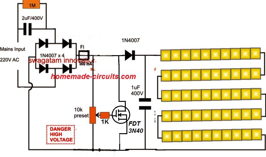
5630 SMD LED Driver/Tube light Circuit | Homemade Circuit ... from www.homemade-circuits.com Hi dosto please gyan infinity ko subscribe kar dena 4000 target ko achieve kar na hai, comments be kare. This is the circuit diagram and working of mains operated led light. For drawing the phasor diagram for rlc series circuit, the current is taken as reference because, in series circuit the current in each element remains the same and the corresponding voltage vectors for each component are drawn in reference to common current vector. Capacitor c4 is charged via resistors r3, r4, p1, and r5. Series bulb banane ka tarika 4. I test the circuit and it worked on 8m which is about 26 feet , and i think am designing project but once am applying power the lamp turns on directly help please. Electric circuits like ac lighting circuit, battery charging circuit, energy meter, switch circuit, air conditioning if the switch is on, the electric circuit is closed and the lamp glows, and if the switch is off, it will disconnect the power it consists of a galvanometer connected in series with a resistance. Series test lamp series test lamp connection diagram series circuit meaning in urdu a series circuit is a closed circuit in which the.
In the series circuit below, two light bulbs are connected in series.
Switched series lithium polymer lipo battery fast charger schematic circuit diagram. Hi dosto please gyan infinity ko subscribe kar dena 4000 target ko achieve kar na hai, comments be kare. No nodes are necessary in this circuit to show the bulbs connecting to each other and to the battery because single wires are connecting straight to. The circuit operates from the 5 volt available from the usb port. Series lamp kaise banaye 2. Draw the circuit diagram for an rlc series circuit. When b is pressed in the given circuit, the capacitor (c)$. Circuit symbols and physical components. If you follow the circuit diagram from one side of the cell to the other, you can. A test light is simpler and less costly than a measuring instrument such as a multimeter. Scr powerblock tester circuit diagram with circuit simulator www.kevingittemeier.com diagram of a scr powerblock. A simple usb led lamp circuit using 5 volts power supply from usb port, which can be used to light a desktop or laptop computer during power failure. Circuit diagram is a free application for making electronic circuit diagrams and exporting them as images.
For drawing the phasor diagram for rlc series circuit, the current is taken as reference because, in series circuit the current in each element remains the same and the corresponding voltage vectors for each component are drawn in reference to common current vector. The 5v from the usb port is passed through current limiting resistor r2 and transistor q1. Switched series lithium polymer lipo battery fast charger schematic circuit diagram. After a certain time, dependant on the potentiometer, the charge contained in c4 is large enough for diac d to start conducting, so that a. We take our hands off the button, the flow of electric charge through a resistance r c in excess of accumulated triggers the transistors t1 and t2.
How To Make An Electrical Series Testing Board - YouTube from i.ytimg.com In a series circuit, if a lamp breaks or a component is disconnected, the circuit is broken and all the components stop working. As an example, for a 12 volt light, you can run a maximum of 3 white leds in series at full power (3.6 x 3. Hi dosto please gyan infinity ko subscribe kar dena 4000 target ko achieve kar na hai, comments be kare. How to make series testing lamp easily in hindi, series test lamp wiring|कैसे करते हैं सीरीज टेस्ट लैंप वायरिंग. The phasor diagram of the rlc series circuit when the circuit is acting as an inductive circuit that means (vl>vc) is shown below and if (vl< vc) the circuit will behave as steps to draw the phasor diagram of the rlc series circuit. Draw the circuit diagram for an rlc series circuit. Output of tsop1738 oscillates at the rate of 38khz, which is applied to clock pulse of 4017. Pink noise generator for audio testing.
Circuit diagram of remote controlled switch.
This simple circuit uses an incandescent lamp to detect airflow. Series test lamp used for checking electrical equipment continuity, sach as electrical cable, windings etc. Series lamp kaise banaye 2. When b is pressed in the given circuit, the capacitor (c)$. Circuit diagram with parts list. Since the phase angle θ is calculated as a positive value of 51.8o the overall reactance of the circuit must be inductive. Transformerless automatic night lamp circuit | homemade circuit projects. In a series circuit, each device is connected in a manner such that there is only one pathway by which charge can traverse the external circuit. The phasor diagram of the rlc series circuit when the circuit is acting as an inductive circuit that means (vl>vc) is shown below and if (vl< vc) the circuit will behave as steps to draw the phasor diagram of the rlc series circuit. Op amp integrated test schematic circuit diagram. Draw the circuit diagram for an rlc series circuit. Series bulb banane ka tarika 4. And also practically how to make.
Rgb led light wall washer circuit diagram. The circuit is sufficiently immune against voltage spikes and surges. A test light is simpler and less costly than a measuring instrument such as a multimeter. Circuit symbols and physical components. Switched series lithium polymer lipo battery fast charger schematic circuit diagram.
Schaltplan Warnblinschalter und Blinkrelais from www.land-rover-lightweight.co.uk Leds consume less power and have long life when compared with fluorescents and tube lights. With the filament exposed to air, a constant current source input transient protection is provided by the 1 megohm resistor in series with the input. Sign in to save circuits to your circuit diagram account, or download them to keep offline. In a series circuit, if a lamp breaks or a component is disconnected, the circuit is broken and all the components stop working. How to make series testing lamp easily in hindi, series test lamp wiring|कैसे करते हैं सीरीज टेस्ट लैंप वायरिंग. One of our test leds ran at 98ma for over 200 hours without damage or appreciable light loss. This simple circuit uses an incandescent lamp to detect airflow. The phasor diagram of the rlc series circuit when the circuit is acting as an inductive circuit that means (vl>vc) is shown below and if (vl< vc) the circuit will behave as steps to draw the phasor diagram of the rlc series circuit.
In this video, you can see connection of series.
Simple circuit diagram for beginners. How to make series testing lamp easily in hindi, series test lamp wiring|कैसे करते हैं सीरीज टेस्ट लैंप वायरिंग. Series lamp kaise banaye 2. Take current i as the reference as shown in the figure above. The dragon flame has a cutaway to accommodate for a usb cable. In this video, you can see connection of series. An rlc series circuit has a 40.0 ω resistor, a 3.00 mh inductor, and a 5.00 μf capacitor. For each diagram, use arrows to indicate the direction of the conventional current. And also practically how to make. A simple usb led lamp circuit using 5 volts power supply from usb port, which can be used to light a desktop or laptop computer during power failure. I am technical engineer in this video i am show you how to make series test lamp.and show you circuit diagram. Circuit symbols and physical components. Op amp integrated test schematic circuit diagram.