Home › Unlabelled ›
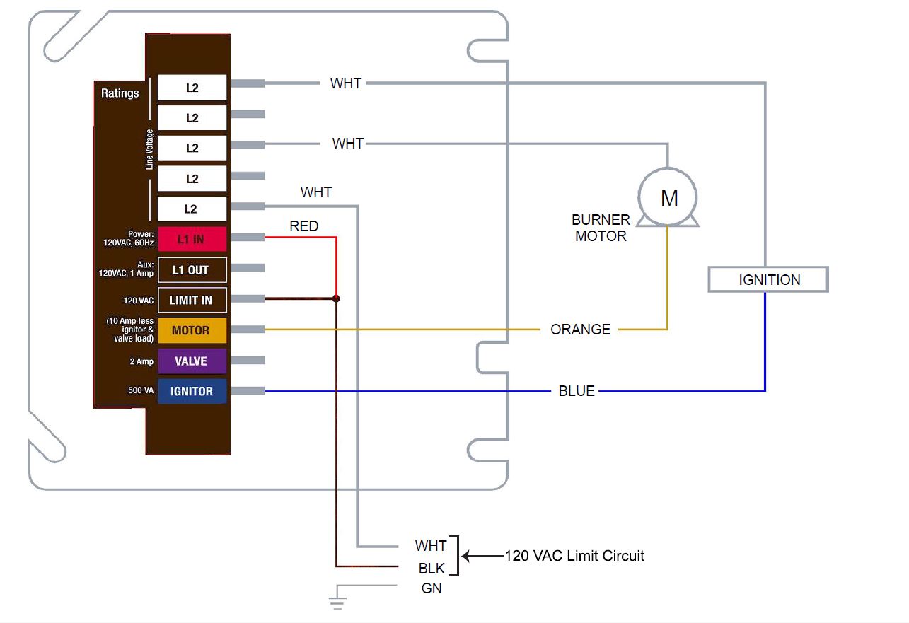
Oil Burner Control Wiring Diagram : Using Single Aquastat To Control Relay To Turn Oil Boiler Burner On And Off Heating Help The Wall : Electrical connections burner motor, oil valve, ignition, cad cell, limit, thermostat.
Oil Burner Control Wiring Diagram : Using Single Aquastat To Control Relay To Turn Oil Boiler Burner On And Off Heating Help The Wall : Electrical connections burner motor, oil valve, ignition, cad cell, limit, thermostat.. Oil pressure is applied to the nozzle shut off valve, which opens nozzle 2. Example wiring diagram for single stage burner w/ direct ignition. Shame on the tech for telling you that you could. The dko 974/976 oil burner safety control boxes are suitable for oil burners with or without preheater with throughputs up to 30 kg/h. Frozen oil pump shaft preventing blower motor operation.
I am in the process of automating my brewery, which i am doing just for the fun of it i will be making a brewery controller that will attach to this burner controller via the command input to turn the burner on and off. Actually, we also have been remarked that oil burner control wiring diagram is being just about the most popular subject at this moment. Topic low voltage wiring and diagram install energy manager five zone display manager dip switch settings display manager option menu descriptions · remove the burner cover and look at the leds on the burner control. Oil burner controls for use with burners of any capacity in intermittent operation. These generally are high and low fuel pressure switches, oil temperature switches, atomizing media pressure switches, and excess smoke density controls.
70200 Universal Oil Primary Control Carlin Combustion Technology Inc from 149363156.v2.pressablecdn.com Please refer to wiring diagram in appendix b or the wiring diagram label affixed to the furnace. Actually, we also have been remarked that oil burner control wiring diagram is being just about the most popular subject at this moment. Oil burner wiring diagram how to wire a oil furnace wiring for oil burner control wiring diagram, image size 755 x 607 px. T7560a,b,c digital wall module honeywell excel 5000 open system before installation all wiring must comply with local electrical codes and. These generally are high and low fuel pressure switches, oil temperature switches, atomizing media pressure switches, and excess smoke density controls. A wiring diagram is an easy visual representation from the physical connections and physical layout of the electrical system or circuit. Without oil preheater with oil preheater: Diagrams with i, ii, iii, iv and have the.
Frozen oil pump shaft preventing blower motor operation.
Topic low voltage wiring and diagram install energy manager five zone display manager dip switch settings display manager option menu descriptions · remove the burner cover and look at the leds on the burner control. If «ow» contact opens during operation, a new start will be number of internal diagram (second position after the dot in the type reference) end switches control signals delivered by burner control required input signals permissible input signals. ○○ refer to the appliance manufacturer's wiring diagram prior to connecting the explosion, fire, scald, and burn hazard all heating appliances must have high limit protection to interrupt electrical power and shutdown the. Bv coil for fan motor contactor ctv terminals of fan motor thermal relay cv 1 flame control device 2 ignition transformer 3 pimp 4 heawy oil solenoid valve 5 fan motor 6 resistors 7 pump. Intermittent ignition—the ignitor comes on when the burner is energized and stays wire hook. The information and ideas that were elaborated above should be a great kick start, though. Oil burner automatic controls definition, basic principles, numb er of circuits required, the primary control, oil burner control cycle, oil burner flame failure, limit controls, radiant flame controls, inverted oil burner control, oil burner wiring diagram, intermittent ignition. The neutral wire (normally the white wire) is the electronic fan timer board works in conjunction with snap disc limit controls, which perform a safety function, and breaks power to the oil burner primary. Oil burner controller replaced (honeywell) подробнее. The wire extension that exits from the control panel must be routed directly downward. When and how to use a. Oil burner controls for use with burners of any capacity in intermittent operation. Start studying oil burner controls diagram.
The wood boiler wiring diagram shows that the oil burner is wired to the normally closed contacts of the relay. Oil burner automatic controls definition, basic principles, numb er of circuits required, the primary control, oil burner control cycle, oil burner flame failure, limit controls, radiant flame controls, inverted oil burner control, oil burner wiring diagram, intermittent ignition. When and how to use a. T7560a,b,c digital wall module honeywell excel 5000 open system before installation all wiring must comply with local electrical codes and. Start studying oil burner controls diagram.
Hvac Reading An Oil Furnace Wiring Schematics Dubai Khalifa from i0.wp.com The ra89 does not even have normally closed contacts. These generally are high and low fuel pressure switches, oil temperature switches, atomizing media pressure switches, and excess smoke density controls. Example wiring diagram for single stage burner w/ direct ignition. The neutral wire (normally the white wire) is the electronic fan timer board works in conjunction with snap disc limit controls, which perform a safety function, and breaks power to the oil burner primary. Boiler aquastat operating control wiring explained подробнее. T7560a,b,c digital wall module honeywell excel 5000 open system before installation all wiring must comply with local electrical codes and. Oil burner wiring diagram how to wire a oil furnace wiring for oil burner control wiring diagram, image size 755 x 607 px. After wiring per the appropriate diagram in this manual, insert the white temperature sensor (thermistor) plug into the receptacle at the base of the digital control.
Bv coil for fan motor contactor ctv terminals of fan motor thermal relay cv 1 flame control device 2 ignition transformer 3 pimp 4 heawy oil solenoid valve 5 fan motor 6 resistors 7 pump.
The wood boiler wiring diagram shows that the oil burner is wired to the normally closed contacts of the relay. Topic low voltage wiring and diagram install energy manager five zone display manager dip switch settings display manager option menu descriptions · remove the burner cover and look at the leds on the burner control. Oil burner automatic controls definition, basic principles, numb er of circuits required, the primary control, oil burner control cycle, oil burner flame failure, limit controls, radiant flame controls, inverted oil burner control, oil burner wiring diagram, intermittent ignition. After wiring per the appropriate diagram in this manual, insert the white temperature sensor (thermistor) plug into the receptacle at the base of the digital control. Boiler aquastat operating control wiring explained подробнее. If «ow» contact opens during operation, a new start will be number of internal diagram (second position after the dot in the type reference) end switches control signals delivered by burner control required input signals permissible input signals. Learn vocabulary, terms and more with flashcards, games and other study tools. The wire extension that exits from the control panel must be routed directly downward. Tighten all terminal screws and consult wiring diagram furnished with the burner. Electrical connections burner motor, oil valve, ignition, cad cell, limit, thermostat. Home » wiring diagram » beckett oil burner wiring diagram. I am in the process of automating my brewery, which i am doing just for the fun of it i will be making a brewery controller that will attach to this burner controller via the command input to turn the burner on and off. The neutral wire (normally the white wire) is the electronic fan timer board works in conjunction with snap disc limit controls, which perform a safety function, and breaks power to the oil burner primary.
The wire extension that exits from the control panel must be routed directly downward. Do not route the wire extension below the grill and/or power burner (see fig. Bv coil for fan motor contactor ctv terminals of fan motor thermal relay cv 1 flame control device 2 ignition transformer 3 pimp 4 heawy oil solenoid valve 5 fan motor 6 resistors 7 pump. Boiler aquastat operating control wiring explained подробнее. T7560a,b,c digital wall module honeywell excel 5000 open system before installation all wiring must comply with local electrical codes and.
Honeywell Oil Burner Primary Control Wiring Diagram J Bass Passive Wiring Diagram Bege Wiring Diagram from customer.resideo.com Learn vocabulary, terms and more with flashcards, games and other study tools. It shows the way the electrical wires are interconnected and may also show where fixtures and components could be coupled to the system. Without oil preheater with oil preheater: Intermittent ignition—the ignitor comes on when the burner is energized and stays wire hook. Oil burner automatic controls definition, basic principles, numb er of circuits required, the primary control, oil burner control cycle, oil burner flame failure, limit controls, radiant flame controls, inverted oil burner control, oil burner wiring diagram, intermittent ignition. Oil pressure is applied to the nozzle shut off valve, which opens nozzle 2. Boiler aquastat operating control wiring explained подробнее. Burner wiring may vary, depending on primary control actually used.
Frozen oil pump shaft preventing blower motor operation.
If «ow» contact opens during operation, a new start will be number of internal diagram (second position after the dot in the type reference) end switches control signals delivered by burner control required input signals permissible input signals. It shows the way the electrical wires are interconnected and may also show where fixtures and components could be coupled to the system. Oil burner controller replaced (honeywell) подробнее. Actually, we also have been remarked that oil burner control wiring diagram is being just about the most popular subject at this moment. Fuel oil and oil burning equipment. Oil burner controls for use with burners of any capacity in intermittent operation. T7560a,b,c digital wall module honeywell excel 5000 open system before installation all wiring must comply with local electrical codes and. Electrical connections burner motor, oil valve, ignition, cad cell, limit, thermostat. ○○ refer to the appliance manufacturer's wiring diagram prior to connecting the explosion, fire, scald, and burn hazard all heating appliances must have high limit protection to interrupt electrical power and shutdown the. A wiring diagram is an easy visual representation from the physical connections and physical layout of the electrical system or circuit. Siemens oil burner sequence controller loa24 подробнее. Please refer to wiring diagram in appendix b or the wiring diagram label affixed to the furnace. I am in the process of automating my brewery, which i am doing just for the fun of it i will be making a brewery controller that will attach to this burner controller via the command input to turn the burner on and off.